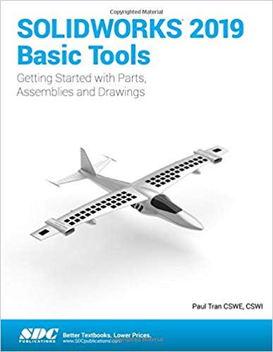
SOLIDWORKS 2019 Basic Tools (10th edition) - Image pdf with ocr

دانلود کتاب SOLIDWORKS 2019 Basic Tools (10th edition) - Image pdf with ocr

Author: Paul Tran

0 (0)

توضیحات کتاب :

SOLIDWORKS Basic Tools is the first book in a three part series

سرچ در وردکت | سرچ در گودریدز | سرچ در اب بوکز | سرچ در آمازون | سرچ در گوگل بوک

1,404 بازدید 5 خرید

ضمانت بازگشت

ضمانت بازگشت

فایل های تست شده

فایل های تست شده

پرداخت آنلاین

پرداخت آنلاین

تضمین کیفیت

تضمین کیفیت

دانلود فوری

دانلود فوری

SOLIDWORKS Basic Tools is the first book in a three part series. It introduces new users to the SOLIDWORKS interface, SOLIDWORKS tools and basic modeling techniques. It provides you with a strong understanding of SOLIDWORKS and covers the creation of parts, assemblies and drawings. Every lesson and exercise in this book was created based on real world projects. Each of these projects has been broken down and developed into easy and comprehensible steps. Furthermore, at the end of every chapter there are self test questionnaires to ensure that you have gained sufficient knowledge from each section before moving on to more advanced lessons. This book takes the approach that in order to understand SOLIDWORKS, inside and out, you should create everything from the beginning and take it step by step.

چکیده فارسی

SOLIDWORKS Basic Tools اولین کتاب از مجموعه سه قسمتی است. کاربران جدید را با رابط SOLIDWORKS، ابزار SOLIDWORKS و تکنیک های مدل سازی اولیه آشنا می کند. درک قوی از SOLIDWORKS برای شما فراهم می کند و ایجاد قطعات، مجموعه ها و نقشه ها را پوشش می دهد. هر درس و تمرین در این کتاب بر اساس پروژه های دنیای واقعی ایجاد شده است. هر یک از این پروژه ها به مراحل آسان و قابل درک تقسیم شده اند. علاوه بر این، در پایان هر فصل پرسشنامه‌های خودآزمایی وجود دارد تا اطمینان حاصل شود که قبل از رفتن به درس‌های پیشرفته‌تر، دانش کافی از هر بخش کسب کرده‌اید. این کتاب این رویکرد را دارد که برای درک SOLIDWORKS، درون و بیرون، باید همه چیز را از ابتدا ایجاد کنید و آن را گام به گام پیش ببرید.

ادامه ...

Ebook details:
عنوان: SOLIDWORKS 2019 Basic Tools
نویسنده: Paul Tran
ناشر: SDC Publications; 1 edition (December 5, 2018)
زبان: English
شابک: 1630572284, 978-1630572280
حجم: 138 Mb
فرمت: Image pdf with ocr

ادامه ...

Title Page Copyright Acknowledgments Table of Contents Introduction: SOLIDWORKS 2019 User Interface The 3 reference planes The Toolbars The System Feedback symbols The Status Bar 2D Sketch examples 3D Feature examples Chapter 1: System Options Setting up the System Options The General Options The Drawings Options The Display Style Options The Area Hatch/Fill Options The Performance Options The Colors Options The Sketch Options The Relations / Snaps Options The Display / Selection Options The Performance Options The Assemblies Options The External References Options The Default Templates Options The File Locations Options The Feature- Manager Options The Spin Box Increments Options The View Options The Backups / Recover Options The TouchOptions The Hole- Wizard/Toolbox Options The File Explorer Options The Search Options The Collaboration Options The Messages /Errors/Warnings Options The Import Options The Export Options Questions for Review Chapter 2: Document Templates Setting up the DocumentProperties The Drafting Standard options The Annotations options The Balloons options The Datums options The Geometric Tolerance options The Notes options The Revision Clouds options The Surface Finishes options The Weld Symbols options The Dimensions options The Angle options The Angular Running options The Arc Length options The Chamfer options The Diameter options The Hole Callout options The Linear options The Ordinate options The Radius options The Virtual Sharps options The Tables options The Bill of Materials options The General options The Title Block Table options The DimXpert options The Size Dimension options The Location- Dimension options The Chain Dimension options The Geometric- Tolerance options The Chamfer- Controls options The Display options The Detailing options The Grid/Snap options The Units options The Model Display options The Material Properties options The Image Quality options The Sheet Metal MBD options The Weldments options The Plane Display options The Configurations option Saving the settings as a Part Template Questions for Review Chapter 3: Basic Solid Modeling - Extrude Options Tools Needed Starting a new Part Changing the Scene Starting a new Sketch Using the Click + Hold + Drag technique Adding Geometric Relations Adding a Collinear relation Geometric Relations Examples Adding the horizontal dimensions Adding the Vertical dimensions The Status of a Sketch Hiding the Sketch Relation Symbols Extruding the Base Sketching on a Planar Face Using the Trim Entities command Extruding a Boss Extrude summary Adding the model fillets Questions for Review Using the Search Commands Exercise: Extrude Boss & Extrude Cut Chapter 4: Basic Solid Modeling - Extrude and Revolve Link Components Tools Needed Sketching the first profile Extruding the first solid Creating the Bore holes Cutting the Bore holes Mirroring the Bore holes Extruding a Through All cut Adding fillets Creating the Sub-Components Revolving the base feature Adding chamfers Extruding the base Sketching the Recess Profiles Extruding a blind cut Mirroring the cut Adding the Holes Adding more fillets Questions for Review Exercise: Extrude Boss & Extrude Cut Chapter 5: Revolved Parts Ball Joint Arm Tools Needed Creating the Base Profile Revolving the Base Feature Sketching the Opened-End Profile Revolving the Opened-End Feature Mirroring the Revolved feature Adding Fillets Questions for Review Exercise: Flat Head Screw Driver Derived Sketches Center Ball Joint Tools Needed Creating the Base Profile Revolving the Base Feature Creating a new work plane Creating a Derived Sketch Positioning the Derived Sketch Adding Fillets Questions for Review Exercise: Revolved Parts - Wheel Exercise: Plastic Bottle Chapter 6: Rib & Shell Features Formed Tray Tools Needed Sketching the Base Profile Extruding the Base feature Adding the Side Cutouts Removing more material Creating the Rib Profiles Adding Fillets Shelling the lower portion Questions for Review Shell & Mirror Features - Styrofoam Box Tools Needed Starting a new part Extruding the base Adding fillets Creating an offset sketch Creating a recess Creating the rim Creating the fold feature Mirroring the solid body Creating the lock feature Creating the lock cavity Shelling the part Untitled Chapter 7: Patterns Linear Patterns - Test Tray Tools Needed Sketching the Base Profile Extruding the Base Feature Sketching the seed feature Extruding a seed feature Creating a Linear Pattern Shelling the Base feature Adding Fillets Questions for Review Circular Patterns - Spur Gear Tools Needed Sketching the Body profile Using the Dynamic Mirror Revolving the Base Body Sketching the Thread Profile Converting the entities Trimming the Sketch Entities Adding Dimensions Cutting the First Tooth Circular Patterning the Tooth Adding the Keyway Extruding a Cut Untitled Circular Patterns - Circular Base Mount Tools Needed Creating the Base Sketch Revolving the Base Feature Creating the first Side-Tab sketch Extruding the Side-Tab Adding a Counterbore Hole Creating the circularpattern Creating a new Plane Creating the Pockets Sketch Adding Fillets Questions for Review Curve Driven Pattern and Hole Wizard Tools Needed Opening the existing file Extruding the Base Creating the sketch of the 1st hole Constructing the Curve-Sketch to drive the Pattern Creating the 1st Curve-Driven Pattern Adding the Hole Wizard Creating the 2nd Curve Driven Pattern Chapter 8: Part Configurations Machined Block Tools Needed Sketching the base profile Extruding the base feature Creating the pocket profiles Adding a CounterBore from the Hole Wizard Patterning the Counterbore Creating the Mirror-Plane Mirroring the C’bores Creating the blind holes Creating a Cutaway section Sketching a profile for the cut Creating the section cut Switching between the Configurations Splitting the FeatureManager pane Creating a new configuration Questions for Review Exercise 1: Using Vary-Sketch Exercise 2: Using Vary-Sketch Chapter 9: Modeling Threads Threaded Insert Tools Needed Sketching the base profile Revolving the base feature Creating the right hand threads Using the Mirror Bodies option Adding chamfers Questions for Review Exercise: Modeling Threads - Internal Exercise: Internal Threads Exercise: External Threads Chapter 10: Bottom Up Assembly Ball Joint Assembly Tools Needed Starting a new Assembly template Inserting the components Mating the components Moving the component Inserting another instance into the assembly Constraining the components Questions for Review Bottom Up Assembly - Links Assembly Tools Needed Starting a new Assembly Template Placing the 1st Component Adding other components Changing colors Inserting the Single Link into the assembly Using the Selection Filters Adding Mates Adding a Width mate Making copies of the component Inserting other components into the Assembly Rotating the Pin Head Constraining the Alignment Pin Constraining the Pin-Head Using the Align & Anti-Align Options Questions for Review Exercise: Gate Assembly Chapter 11: Using Advanced Mates Rack and Pinion Open an assembly document Adding standard mates Suppressing a mate Adding a Mechanical mate Testing the mates Creating a Linear Motion Limit & Cam Mates Opening a part file Adding a Width mate Adding a Cam mate Adding a Parallel mate Adding a Limit mate Exercise: Cam Followers Questions for Review Exercise: Bottom Up Assembly Level 1 Final Exam: Assembly Motions Chapter 12: Layout Assembly Assembly Motions Tools Needed Opening an assembly document Activating the layout mode Creating a new sketch Making a Block Setting the Insertion Point Editing a block Adding dimensions Testing the relations between the blocks Converting a Block into a Component Extruding the Fixed Base Adding fillets Shelling the part Adding a hole Converting the next block Extruding the Arm Adding a cut Using the Extrude-From option Hiding the sketches Viewing the Assembly Motions SOLIDWORKS Animator – The Basics Opening an existing Assembly document Adding a Rotary Motor Viewing the rotary motions Using the Animation Wizard Animating the Explode of an Assembly Animating the Collapse of the Assembly Changing the View Orientation of the assembly Looping the animation Saving the animation as AVI Viewing the Egg Beater AVI with Windows Media Player Chapter 13: PhotoView 360 Basics Activating PhotoView 360 Setting the Appearance Setting the Scene Setting the Image Quality options Rendering the image Exercise: HeliDrone Assembly Rendering the Screen with Ambient Occlusion Opening an assembly document Changing the scene Retrieving a Named View Applying appearances to the components Chapter 14: Drawing Preparations Customizing the Document Template Tools Needed Setting up a new drawing Switching to the Sheet Format layer Switching back to the Sheet layer Setting up the Drawing Options Setting up the Document Template options Saving the Document Template Questions for Review Chapter 15: Assembly Drawings Links Assembly Tools Needed Creating a new drawing Editing the Sheet Format Setting up the anchor point to attach the B.O.M. Switching back to the Sheet layer Opening an existing assembly document Switching to the Exploded View state Changing the Line Style Using the View Palette Switching to Shaded view Adding the Bill of Materials (B.O.M.) to the drawing Selecting the B.O.M. options Modifying the B.O.M. Reversing the column headers Adding Balloon callouts Changing the balloon style Questions for Review Exercise: Assembly Drawings Alternate Position Views Tools Needed Creating a new drawing Creating the Isometric Drawing View Changing the Drawing View Scale Creating an Alternate Position drawing view Adding the Top Drawing view Adding Text / Annotations Creating an Exploded Isometric view Adding Auto-Balloons to the Exploded view Adding the Bill of Materials Untitled Chapter 16: Drawing Views Machined Block Tools Needed Creating a new drawing Editing the Sheet Format Modifying the existing text Adding the Title of the drawing Using the View-Palette Adding an Isometric view Moving the drawing view(s) Breaking the alignments between the views Creating a Detail View Using the Detail View options Creating a Projected View Creating an Auxiliary View Creating a Section View Showing the hidden lines in a drawing view Creating a Broken-Out-Section Adding a Cutaway view Changing Configurations Adding crosshatch to the sectioned surfaces Modifying the crosshatch properties Geometric Tolerance & Flag Notes Modifying & Hole Symbols SYMBOL DESCRIPTIONS Chapter 17: Detailing - Machined Block Details Machined Block Details Tools Needed Opening a drawing document Inserting dimensions from the model Re-arranging the new dimensions Inserting dimensions to the Section view Adding dimensions to the Auxiliary view Adding the Center Marks Adding the Datum Feature Symbols Datum Reference & Geometric Tolerance Examples Adding hole specifications using the Hole-Callout Adding Geometric Tolerances Align the Geometric Tolerance Attaching the Geometric Tolerance to the Driving dimension Adding Tolerance/Precision to dimensions Adding Symmetric tolerance to a dimension Adding Surface Finish callouts Adding non-parametric callouts Inserting Notes Changing document’s font Questions for Review Exercise: Detailing I Exercise: Detailing II Fastener Callouts Thread Nomenclature Attaching a note or a symbol to a dimension Chapter 18: Sheet Metal Drawings Post Cap Tools Needed Starting a new drawing Creating the 3 Standard Views Re-arranging the drawing views Creating the Flat-Pattern drawingview Creating a Detail view Adding the Ordinate dimensions Adding the Modeldimensions Creating the Isometric Flat Pattern view Showing /Hiding the Bend Lines eDrawing & 3D Drawing View SOLIDWORKS 2019 - 3D Drawing View Reorienting Views Chapter 19: Configurations Part I: Part, Assembly & Drawing Tools Needed Opening an Assembly Document Using Configurations in the Part mode Changing the Pitch Creating an Assembly Configuration Changing the Mate conditions Adding new Mates Changing Configuration Using Configurations in a Drawing Changing the Configuration of a drawing view Part II: Part, Assembly & Drawing Tools Needed Part Configurations Opening a part document Creating a new configuration Changing the number of the Spokes Viewing the configurations Assembly Configurations Starting a New assembly Inserting the Sub-Assembly Mating the Sub-Assembly Viewing the Assembly Configurations Drawing Configurations Creating an assembly drawing Creating the standard drawing views Auto-Start the Projected-View Creating the Aligned Section View Creating the Isometric view Displaying the Exploded View Changing Configurations Adding Annotations Chapter 20: Design Tables Tools Needed Copying the document Creating a New Design Table Transferring thedimensions to theDesign Table Using Excel’s Addition Formula Controlling the Suppression-States of the holes Viewing the Configurations generated by the Design Table Assembly - Design Tables Copying the Egg Beater Assembly Creating a new Assembly Design Table Defining the column headers Inserting the Control Parameters Adding the configuration names Assigning the control values Viewing the new configurations Exercise: Part Design Tables Level 2 Final Exam Table of U.S. Measures Table of Metric Measures CSWA Preparation Materials (Certified SOLIDWORKS Associate) Preparation materials for the CSWA examination Drafting competencies Basic Part Modeling Bottom Up Assembly 1 Bottom Up Assembly 2 Glossary Index SOLIDWORKS 2019 Quick Guide

ادامه ...
برای ارسال نظر لطفا وارد شوید یا ثبت نام کنید
ادامه ...
پشتیبانی محصول

۱- در صورت داشتن هرگونه مشکلی در پرداخت، لطفا با پشتیبانی تلگرام در ارتباط باشید.

۲- برای خرید محصولات لطفا به شماره محصول و عنوان دقت کنید.

۳- شما می توانید فایلها را روی نرم افزارهای مختلف اجرا کنید(هیچگونه کد یا قفلی روی فایلها وجود ندارد).

۴- بعد از خرید، محصول مورد نظر از صفحه محصول قابل دانلود خواهد بود همچنین به ایمیل شما ارسال می شود.

۵- در صورت وجود هر مشکلی در فرایند خرید با تماس بگیرید.