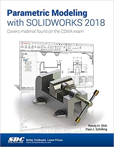
Parametric Modeling with SOLIDWORKS 2018 - Image pdf with ocr

دانلود کتاب Parametric Modeling with SOLIDWORKS 2018 - Image pdf with ocr

Author: Paul Schilling, Randy Shih

0 (0)

توضیحات کتاب :

Parametric Modeling with SOLIDWORKS 2018 contains a series of seventeen tutorial style lessons designed to introduce SOLIDWORKS 2018, solid modeling and parametric modeling techniques and concepts

سرچ در وردکت | سرچ در گودریدز | سرچ در اب بوکز | سرچ در آمازون | سرچ در گوگل بوک

1,296 بازدید 1 خرید

ضمانت بازگشت

ضمانت بازگشت

فایل های تست شده

فایل های تست شده

پرداخت آنلاین

پرداخت آنلاین

تضمین کیفیت

تضمین کیفیت

دانلود فوری

دانلود فوری

Parametric Modeling with SOLIDWORKS 2018 contains a series of seventeen tutorial style lessons designed to introduce SOLIDWORKS 2018, solid modeling and parametric modeling techniques and concepts. This book introduces SOLIDWORKS 2018 on a step-by-step basis, starting with constructing basic shapes, all the way through to the creation of assembly drawings and motion analysis.

This book takes a hands on, exercise intensive approach to all the important parametric modeling techniques and concepts. Each lesson introduces a new set of commands and concepts, building on previous lessons. The lessons guide the user from constructing basic shapes to building intelligent solid models, assemblies and creating multi-view drawings.

This book also covers some of the more advanced features of SOLIDWORKS 2018, including how to use the SOLIDWORKS Design Library, basic motion analysis, collision detection and analysis with SimulationXpress.


چکیده فارسی

مدل‌سازی پارامتریک با SOLIDWORKS 2018 شامل مجموعه‌ای از هفده درس سبک آموزشی است که برای معرفی SOLIDWORKS 2018، تکنیک‌ها و مفاهیم مدل‌سازی جامد و مدل‌سازی پارامتریک طراحی شده‌اند. این کتاب SOLIDWORKS 2018 را به صورت گام به گام معرفی می‌کند و با ساختن شکل‌های اولیه شروع می‌شود و تا ایجاد نقشه‌های مونتاژ و تحلیل حرکت شروع می‌شود.

این کتاب رویکردی فشرده به تمام تکنیک‌ها و مفاهیم مهم مدل‌سازی پارامتری دارد. هر درس مجموعه جدیدی از دستورات و مفاهیم را معرفی می کند که بر اساس درس های قبلی است. این درس ها کاربر را از ساختن اشکال اولیه تا ساخت مدل های جامد هوشمند، مجموعه ها و ایجاد نقشه های چند نمای راهنمایی می کند.

این کتاب همچنین برخی از ویژگی‌های پیشرفته‌تر SOLIDWORKS 2018 را پوشش می‌دهد، از جمله نحوه استفاده از کتابخانه طراحی SOLIDWORKS، تجزیه و تحلیل اولیه حرکت، تشخیص برخورد و تجزیه و تحلیل با SimulationXpress.

ادامه ...

Ebook details:
عنوان: Parametric Modeling with SOLIDWORKS 2018
نویسنده: Paul Schilling, Randy Shih
ناشر: CRC Press; 1 edition (April 6, 2018)
زبان: English
شابک: 1630571415, 978-1630571412
حجم: 155 Mb
فرمت: Image pdf with ocr

ادامه ...

Preface Acknowledgments Table of Contents Certified SOLIDWORKS Associate (CSWA) Exam Overview Chapter 1: Introduction – Getting Started Introduction Development of Computer Geometric Modeling Feature-Based Parametric Modeling Getting Started with SOLIDWORKS Units Setup SOLIDWORKS Screen Layout Mouse Buttons [Esc] – Canceling Commands Online Help SOLIDWORKS Search Leaving SOLIDWORKS Creating a CAD Files Folder Chapter 2: Parametric Modeling Fundamentals Introduction The Adjuster Design Starting SOLIDWORKS SOLIDWORKS Screen Layout Units Setup Creating Rough Sketches Step 1: Creating a Rough Sketch Graphics Cursors Geometric Relation Symbols Step 2: Apply/Modify Relations and Dimensions Changing the Dimension Standard Viewing Functions – Zoom and Pan Modifying the Dimensions of the Sketch Step 3: Completing the Base Solid Feature Isometric View Rotation of the 3D Model – Rotate View Rotation and Panning – Arrow Keys Viewing – Quick Keys Viewing Tools – Heads-up View Toolbar View Orientation Display Style Orthographic vs. Perspective Sketch Plane Step 4-1: Adding an Extruded Boss Feature Step 4-2: Adding an Extruded Cut Feature Save the Part File Questions Exercises Chapter 3: Constructive Solid Geometry Concepts Introduction Binary Tree The Locator Design Modeling Strategy – CSG Binary Tree Starting SOLIDWORKS and Activating the CommandManager GRID and SNAP Intervals Setup Base Feature Modifying the Dimensions of the Sketch Repositioning Dimensions Completing the Base Solid Feature Creating the Next Solid Feature Creating an Extruded Cut Feature Creating a Hole with the Hole Wizard Creating a Rectangular Extruded Cut Feature Using the View Selector Questions Exercises Chapter 4: Feature Design Tree Introduction Starting SOLIDWORKS Creating a User-Defined Part Template The Saddle Bracket Design Modeling Strategy The SOLIDWORKS FeatureManager Design Tree Creating the Base Feature Adding the Second Solid Feature Creating a 2D Sketch Renaming the Part Features Adjusting the Width of the Base Feature Adding a Hole Creating a Rectangular Extruded Cut Feature History-Based Part Modifications A Design Change FeatureManager Design Tree Views Selecting a Material and Viewing the Mass Properties Questions Exercises Chapter 5: Geometric Relations Fundamentals DIMENSIONS and RELATIONS Create a Simple Triangular Plate Design Fully Defined Geometry Starting SOLIDWORKS and Activating the CommandManager Displaying Existing Relations Applying Geometric Relations/Dimensional Constraints Over-Defining and Driven Dimensions Deleting Existing Relations Using the Fully Define Sketch Tool Adding Additional Geometry Relations Settings Parametric Relations Dimensional Values and Dimensional Variables Parametric Equations Viewing the Established Equations Global Variables Viewing/Editing Equations and Global Variables Using the Dimension Modify Dialog Box View Options in the Equations, Global Variables, and Dimensions Dialog Box Direct Input of Equations in PropertyManager Fields Completing and Saving the Part File Questions Exercises Chapter 6: Geometric Construction Tools Introduction The Gasket Design Modeling Strategy Starting SOLIDWORKS Creating a 2D Sketch Editing the Sketch by Dragging the Entities Adding Additional Relations Using the Trim and Extend Commands Adding Dimensions with the Fully Define Sketch Tool Fully Defined Geometry Creating Fillets and Completing the Sketch Profile Sketch Redefining the Sketch and Profile using Contour Selection Selecting Items by Box and Lasso Create an OFFSET Extruded Cut Feature Alternate Construction Method – Thin Feature Option Questions Exercises Chapter 7: Parent/Child Relationships and the BORN Technique Introduction The BORN Technique The U-Bracket Design Starting SOLIDWORKS and Activating the CommandManager Applying the BORN Technique Creating the 2D Sketch for the Base Feature Creating the First Extrude Feature The Implied Parent/Child Relationships Creating the Second Solid Feature Creating the First Extruded Cut Feature Creating the Second Extruded Cut Feature Examining the Parent/Child Relationships Modify a Parent Dimension A Design Change Feature Suppression A Different Approach to the CENTER_DRILL Feature Suppress the Rect_Cut Feature Creating a Circular Extruded Cut Feature A Flexible Design Approach Save Part File Questions Exercises Chapter 8: Part Drawings and Associative Functionality Drawings from Parts and Associative Functionality Starting SOLIDWORKS Drawing Mode Setting Document Properties Setting Sheet Properties Using the Pre-Defined Sheet Formats Creating Three Standard Views Repositioning Views Adding a New Sheet Adding a Base View Adding an Isometric View using the View Palette Adjusting the View Scale Displaying Feature Dimensions Repositioning, Appearance, and Hiding of Feature Dimensions Adding Additional Dimensions – Reference Dimensions Tangent Edge Display Adding Center Marks, Center Lines, and Sketch Objects Edit Sheet vs. Edit Sheet Format Completing the Drawing Sheet Property Links Associative Functionality – Modifying Feature Dimensions Saving the Drawing File Saving a Drawing Template Questions Exercises Chapter 9: Reference Geometry and Auxiliary Views Reference Geometry Auxiliary Views in 2D Drawings The Rod-Guide Design Modeling Strategy Starting SOLIDWORKS Applying the BORN Technique Creating the Base Feature Creating an Angled Reference Plane Creating a 2D Sketch on the Reference Plane Using the Convert Entities Option Completing the Solid Feature Creating an Offset Reference Plane Creating another Extruded Cut Feature Using the Reference Plane Starting a New 2D Drawing and Adding a Base View Creating an Auxiliary View Displaying Feature Dimensions Adjusting the View Scale Repositioning, Appearance, and Hiding of Feature Dimensions Tangent Edge Display Adding Center Marks and Center Lines Controlling the View and Sheet Scales Completing the Drawing Sheet Editing the Isometric View Questions Exercises Chapter 10: Introduction to 3D Printing What is 3D Printing? Development of 3D Printing Technologies Primary Types of 3D Printing Processes Primary 3D Printing Materials for FDM and FFF From 3D Model to 3D Printed Part Starting SOLIDWORKS Export the Design as an STL File Using the 3D Printing Software to Create the 3D Print Questions Chapter 11: Symmetrical Features in Designs Introduction A Revolved Design: PULLEY Modeling Strategy – A Revolved Design Starting SOLIDWORKS Creating the 2D Sketch for the Base Feature Creating the Revolved Feature Mirroring Features Creating an Extruded Cut Feature using Construction Geometry Circular Pattern Drawing Mode – Defining a New Border and Title Block Creating a New Drawing Template Creating Views Retrieve Dimensions – Model Items Command Save the Drawing File Associative Functionality – A Design Change Adding Centerlines to the Pattern Feature Completing the Drawing Questions Exercises Chapter 12: Advanced 3D Construction Tools Introduction A Thin-Walled Design: Dryer Housing Modeling Strategy Starting SOLIDWORKS Creating the 2D Sketch for the Base feature Create a Revolved Boss Feature Creating Offset Reference Planes Creating 2D Sketches on the Reference Planes Creating a Lofted Feature Creating an Extruded Boss Feature Completing the Extruded Boss Feature Creating 3D Rounds and Fillets Creating a Shell Feature Creating a Rectangular Extruded Cut Feature Creating a Linear Pattern Creating a Swept Feature Using PhotoView 360, Scenes, and Appearances Questions Exercises Chapter 13: Sheet Metal Designs Sheet Metal Processes Sheet Metal Modeling K-Factor The Actuator Bracket Design Starting SOLIDWORKS and Opening the Sheet Metal Toolbar Creating the Base Feature of the Design Creating an Edge Flange Adding a Tab Creating a Cut Feature Creating a Bend Flattening the Sheet Metal Part Confirm the Flattened Length Creating a Sheet Metal Drawing Sheet Metal Bend Notes Completing the Drawing Questions Exercises Chapter 14: Assembly Modeling – Putting It All Together Introduction Assembly Modeling Methodology The Shaft Support Assembly Parts Creating the Collar Using the Chamfer Command Creating the Bearing and Base-Plate Creating the Cap-Screw Starting SOLIDWORKS Document Properties Inserting the First Component Inserting the Second Component Degrees of Freedom Assembly Mates Apply the First Assembly Mate Apply a Second Mate Constrained Move Apply a Third Mate Inserting the Third Component Applying Concentric and Coincident Mates Assemble the Cap-Screws using SmartMates Exploded View of the Assembly Save the Assembly Model Editing the Components Set up a Drawing of the Assembly Model Creating a Bill of Materials Editing the Bill of Materials Completing the Assembly Drawing Exporting the Bill of Materials Questions Exercises Chapter 15: Design Library and Basic Motion Study Introduction The Crank-Slider Assembly Creating the Required Parts Mate References Starting SOLIDWORKS Document Properties Inserting the First Component Inserting the Second Component Apply Assembly Mates Apply a Mate Using a Context Toolbar Constrained Move Placing the Third Component Using a Mate Reference Assemble the CS-Rod Part Inserting a Pin from the SOLIDWORKS Toolbox Assemble the CS-Slider Part Adding an Angle Mate Collision Detection Editing the CS-Slider Part in the Assembly Basic Motion Analysis Questions Exercises Chapter 16: Design Analysis with SimulationXpress Introduction The SimulationXpress Wizard Interface Problem Statement Preliminary Analysis SOLIDWORKS SimulationXpress Study of the Flat Plate Getting Started – Create the SOLIDWORKS Part Create a SimulationXpress Study Viewing SimulationXpress Results Creating a Report and an eDrawings File Accuracy of Results Closing SimulationXpress and Saving Results Questions Exercises Chapter 17: CSWA Exam Preparation Tips about Taking the Certified SOLIDWORKSAssociate (CSWA) Examination Introduction The Part Problem Strategy for Aligning the Part to the Default Axis System Creating the Base Feature Creating a New View Orientation Completing the Part Selecting the Material and Viewing the Mass Properties The Assembly Problem Creating the Parts Creating a Reference Coordinate System View the Mass Properties Questions Exercises Appendix INDEX Blank Page

ادامه ...
برای ارسال نظر لطفا وارد شوید یا ثبت نام کنید
ادامه ...
پشتیبانی محصول

۱- در صورت داشتن هرگونه مشکلی در پرداخت، لطفا با پشتیبانی تلگرام در ارتباط باشید.

۲- برای خرید محصولات لطفا به شماره محصول و عنوان دقت کنید.

۳- شما می توانید فایلها را روی نرم افزارهای مختلف اجرا کنید(هیچگونه کد یا قفلی روی فایلها وجود ندارد).

۴- بعد از خرید، محصول مورد نظر از صفحه محصول قابل دانلود خواهد بود همچنین به ایمیل شما ارسال می شود.

۵- در صورت وجود هر مشکلی در فرایند خرید با تماس بگیرید.