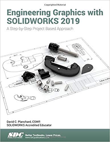
Engineering Graphics with SOLIDWORKS 2019 - Image Pdf

دانلود کتاب Engineering Graphics with SOLIDWORKS 2019 - Image Pdf

Author: David Planchard

0 (0)

توضیحات کتاب :

Engineering Graphics with SOLIDWORKS 2019 is written to assist students, designers, engineers and professionals who are new to SOLIDWORKS

سرچ در وردکت | سرچ در گودریدز | سرچ در اب بوکز | سرچ در آمازون | سرچ در گوگل بوک

1,369 بازدید 2 خرید

ضمانت بازگشت

ضمانت بازگشت

فایل های تست شده

فایل های تست شده

پرداخت آنلاین

پرداخت آنلاین

تضمین کیفیت

تضمین کیفیت

دانلود فوری

دانلود فوری

Engineering Graphics with SOLIDWORKS 2019 is written to assist students, designers, engineers and professionals who are new to SOLIDWORKS.

The book is divided into four sections: Chapters 1 - 3 explore the history of engineering graphics, manual sketching techniques, orthographic projection, Third vs. First angle projection, multi-view drawings, dimensioning practices (ASME Y14.5-2009 standard), line type, fit type, tolerance, fasteners in general, general thread notes and the history of CAD leading to the development of SOLIDWORKS.

Chapters 4 - 9 explore the SOLIDWORKS User Interface and CommandManager, Document and System properties, simple machine parts, simple and complex assemblies, proper design intent, design tables, configurations, multi-sheet, multi-view drawings, BOMs, and Revision tables using basic and advanced features.

Follow the step-by-step instructions in over 80 activities to develop eight parts, four sub-assemblies, three drawings and six document templates.

Chapter 10 provides a section on the Certified Associate - Mechanical Design (CSWA) program with sample exam questions and initial and final SOLIDWORKS models.

Chapter 11 helps you understand the differences between additive and subtractive manufacturing. Comprehend 3D printer terminology along with a working knowledge of preparing, saving, and printing a 3D CAD model on a low cost printer.

Review individual features, commands, and tools. The chapter exercises analyze and examine usage competencies based on the chapter objectives. The book is designed to complement the SOLIDWORKS Tutorials located in the SOLIDWORKS Help menu.

Desired outcomes and usage competencies are listed for each project. Know your objectives up front. Follow the step-by step procedures to achieve your design goals. Work between multiple documents, features, commands, and properties that represent how engineers and designers utilize SOLIDWORKS in industry. The author developed the industry scenarios by combining his own industry experience with the knowledge of engineers, department managers, vendors, and manufacturers.

These professionals are directly involved with SOLIDWORKS every day. Their responsibilities go far beyond the creation of just a 3D model.

Table of Contents

Introduction
1. History of Engineering Graphics
2. Isometric Projection and Multi View Drawings
3. Dimensioning Practices, Scales, Tolerancing and Fasteners
4. Overview of SolidWorks and the User Interface
5. Introduction to SOLIDWORKS Part Modeling
6. Revolved Boss/Base Features
7. Swept, Lofted, Rib, Mirror and Additional Features
8. Assembly Modeling - Bottom up method
9. Fundamentals of Drawing
10. Introduction to the Certified Associate - Mechanical Design (CSWA) Exam
11. Additive Manufacturing - 3D Printing
Appendix
Glossary
Index

چکیده فارسی

Engineering Graphics with SOLIDWORKS 2019 برای کمک به دانشجویان، طراحان، مهندسان و متخصصان تازه کار SOLIDWORKS نوشته شده است.

این کتاب به چهار بخش تقسیم می‌شود: فصل‌های 1 تا 3 به بررسی تاریخچه گرافیک مهندسی، تکنیک‌های طراحی دستی، طرح‌ریزی املایی، طرح‌ریزی زاویه سوم در مقابل اول، نقشه‌های چند نمای، شیوه‌های اندازه‌گیری (ASME Y14.5-2009) می‌پردازد. استاندارد)، نوع خط، نوع تناسب، تلورانس، اتصال دهنده ها به طور کلی، نکات کلی موضوع و تاریخچه CAD که منجر به توسعه SOLIDWORKS شده است.

فصل‌های 4 تا 9 رابط کاربری SOLIDWORKS و CommandManager، ویژگی‌های سند و سیستم، قطعات ساده ماشین، مجموعه‌های ساده و پیچیده، هدف طراحی مناسب، جداول طراحی، پیکربندی‌ها، چند برگه، نقشه‌های چند نمایه، BOM و جداول تجدید نظر با استفاده از ویژگی های اولیه و پیشرفته.

دستورالعمل‌های گام به گام را در بیش از ۸۰ فعالیت برای توسعه هشت بخش، چهار مجموعه فرعی، سه طرح و شش الگوی سند دنبال کنید.

فصل 10 بخشی را در مورد برنامه کاردانی خبره - طراحی مکانیکی (CSWA) با نمونه سوالات امتحانی و مدل های اولیه و نهایی SOLIDWORKS ارائه می دهد.

فصل 11 به شما کمک می‌کند تفاوت‌های بین تولید افزایشی و کاهشی را درک کنید. اصطلاحات چاپگر سه بعدی را همراه با دانش کاری در مورد تهیه، ذخیره و چاپ یک مدل سه بعدی CAD در یک چاپگر کم هزینه درک کنید.

ویژگی‌ها، فرمان‌ها و ابزارهای فردی را مرور کنید. تمرین‌های فصل، شایستگی‌های استفاده را بر اساس اهداف فصل تحلیل و بررسی می‌کنند. این کتاب برای تکمیل آموزش های SOLIDWORKS واقع در منوی راهنمای SOLIDWORKS طراحی شده است.

نتایج مورد نظر و شایستگی های استفاده برای هر پروژه فهرست شده است. اهداف خود را از قبل بشناسید مراحل گام به گام را برای دستیابی به اهداف طراحی خود دنبال کنید. بین چندین سند، ویژگی‌ها، فرمان‌ها و ویژگی‌ها کار کنید که نشان‌دهنده نحوه استفاده مهندسان و طراحان از SOLIDWORKS در صنعت است. نویسنده سناریوهای صنعت را با ترکیب تجربه صنعت خود با دانش مهندسان، مدیران بخش، فروشندگان و تولیدکنندگان توسعه داده است.

این متخصصان هر روز مستقیماً با SOLIDWORKS درگیر هستند. مسئولیت آنها بسیار فراتر از ایجاد یک مدل سه بعدی است.

فهرست محتوا

مقدمه
1. تاریخچه گرافیک مهندسی
2. طرح ریزی ایزومتریک و نقشه های چند نمایشی
3. روش‌های اندازه‌گیری، مقیاس‌ها، تحمل‌کننده‌ها و بست‌ها
4. مروری بر SolidWorks و رابط کاربری
5. مقدمه ای بر مدل سازی قطعات SOLIDWORKS
6. Revolved Boss/Base Features
7. Swept، Lofted، Rib، Mirror و ویژگی های اضافی
8. مدلسازی اسمبلی - روش از پایین به بالا
9. مبانی ترسیم
10. مقدمه ای بر آزمون کاردانی گواهی شده - طراحی مکانیک (CSWA)
11. ساخت افزودنی - چاپ سه بعدی
ضمیمه
واژه نامه
فهرست

ادامه ...

Ebook details:
عنوان: Engineering Graphics with SOLIDWORKS 2019
نویسنده: David Planchard
ناشر: SDC Publications (December 3, 2018)
زبان: English
شابک: 1630572306, 978-1630572303
حجم: 137 Mb
فرمت: Image Pdf

ادامه ...

Title Page Copyright Introduction About the Author Dedication Contact the Author Note to Instructors Trademarks, Disclaimer, and Copyrighted Material References Table of Contents Overview of Chapters Chapter 1: History of Engineering Graphics Chapter 2: Isometric Projection and Multi View Drawings Chapter 3: Dimensioning Practices, Scales, Tolerancing and Fasteners Chapter 4: Overview of SOLIDWORKS 2019 and the User Interface Chapter 5: Introduction to SOLIDWORKS Part Modeling Chapter 6: Revolved Boss/Base Features Chapter 7: Swept, Lofted, Rib, Mirror and Additional Features Chapter 8: Assembly Modeling - Bottom-up method Chapter 9: Drawing Fundamentals Chapter 10: Introduction to the Certified SOLIDWORKS Associate (CSWA) Exam Chapter 11: Additive Manufacturing - 3D Printing About the Book Windows Terminology in SOLIDWORKS Chapter 1 - History of Engineering Graphics Chapter Overview History of Engineering Graphics Global and Local Coordinate System 2 Dimensional Cartesian Coordinate System 3 Dimensional Cartesian Coordinate System Absolute Coordinates Relative Coordinates Polar Coordinates Cylindrical and Spherical Coordinates Freehand Sketching General Sketching Techniques Geometric Entities Points Lines Planes Circles Arcs Solid Primitives Alphabet of Lines Visible lines Hidden lines Dimension lines Extension lines Leader lines Break lines Centerlines Phantom lines Section lines Cutting Plane lines Precedence of Line Types Alphabet of Lines Exercises Projections in General Projection Types Parallel Projection Perspective Projection Orthographic Projection Oblique Projection Multi-view Projections Orient and Select the Front View Orthographic Projection (Third Angle) Glass Box and Six Principal Orthographic Views Height, Width, and Depth Dimensions Transferring Dimensions Sheet Media ANSI Standard Sheet Sizes Orthographic Projection Exercises Planes (Normal, Inclined and Oblique) Plane Exercises Chapter Summary Questions/Exercises Chapter 2 - Isometric Projection and Multi View Drawings Chapter Overview Isometric Projections Isometric Sketching Circles drawn in Axonometric view Additional Projections Oblique projection Arrangement of Views Two-view drawing One-view drawing Drawing Exercises Drawing Views - Advanced Section view Detail View Broken out View Break or Broken View Crop View Auxiliary View Exercises History of Computer Aided Design (CAD) Boolean operations What is SOLIDWORKS? Design Intent Design Intent in a sketch Design intent in a feature Design intent in a part Design intent in an assembly Design intent in a drawing Chapter Summary Questions/Exercises Chapter 3 - Dimensioning Practices, Scales, Tolerancing and Fasteners Chapter Overview American National Standards Institute (ANSI) Dimensioning Location dimension Size dimension Measurement- units Metric/SI English Dual dimensioning Scale Architect’s scale Engineer’s scale Linear encoder Linear scale Vernier scale Standards for Dimensioning Linear dimension Stagger dimension Aligned dimension Angular dimension Chamfer dimension Slot dimension Radius dimension (Leader line) Simple Hole dimension (Leader line) Fastener Hole dimension (Annotations) Cylindrical dimension Equally spaced hole dimension Hole dimension location Point/center of a circle dimension Arc dimension Order of Preference - Linear Dimension line Precision Size Dimension Continuous Dimensions Principles of good dimensioning Precision and Tolerance Tolerance for a drawing General Tolerance - Title Block Local Tolerance - Dimension Limit Tolerance Unilateral Tolerance Bilateral Tolerance Formatting Inch Tolerances Metric Dimension Specifications Tolerance Parts and Important Terms Fit - Hole Tolerance Fit Types between Mating Parts Clearance Fit Interference Fit Transition Fit Fasteners in General Representing External (Male) Threads Cutting External (Male) Threads Die Lathe Representing Internal (Female) Threads Cutting Internal (Female) Threads Taper Plug Bottoming American National Standard and Unified Screw threads Single vs. Double or Triple Threads Pitch and Major Diameter Thread Class of Fit Class 1 Class 2 Class 3 General Thread Notes Dimensioning a Counterbore Hole Dimensioning a Countersunk Hole Chapter Summary Questions/Exercises Chapter 4 - Overview of SOLIDWORKS 2019 and the User Interface Project Objective What is SOLIDWORKS®? Basic concepts in SOLIDWORKS Start a SOLIDWORKS Session Tutorial: Start a SOLIDWORKS Session Welcome dialog box Home Tab Recent Tab Learn Tab Alerts Tab SOLIDWORKS User Interface (UI) and CommandManager Menu Bar toolbar Menu Bar menu Drop-down menu Create a New Part Document Novice Mode Advanced Mode Graphics Window (Default) View Default Sketch Planes Open a Part Part FeatureManager FeatureManager Rollback Bar Heads-up View toolbar Dynamic Annotation Views Zoom to Fit Zoom to Area Window-select Rotate Front View Right View Top View Trimetric View SOLIDWORKS Help SOLIDWORKS Tutorials User Interface Tools Right-click Consolidated toolbar System feedback icon Confirmation Corner Heads-up View toolbar CommandManager (Default Part tab) CommandManager (Default Drawing tab) CommandManager (Default Assembly tab) CommandManager (Float/Fit) Selection Enhancements FeatureManager Design Tree FeatureManager Design Tree tab PropertyManager tab Configuration Manager tab DimXpertManager tab DisplayManager tab CAM tab Hide/Show tab Sensors tool Tags Split Fly-out FeatureManager Task Pane SOLIDWORKS Resources Design Library File Explorer Search View Palette Appearances, Scenes, and Decals Custom Properties SOLIDWORKS Forum User Interface for Scaling High Resolution Screens Motion Study tab 3D Views tab Dynamic Reference Visualization Mouse Movements Single-click Double-click Right-click Scroll wheel Summary Chapter 5 - Introduction to SOLIDWORKS Part Modeling Chapter Overview File Management Start a SOLIDWORKS Session and Open a New Part Document Part Template BATTERY Part BATTERY Part-Extruded Boss/Base Feature BATTERY Part-Fillet Feature Edge BATTERY Part - Extruded Cut Feature BATTERY Part - Fillet Feature BATTERY Part - Extruded Boss/Base Feature BATTERYPLATE Part Save As, Delete, Edit Feature and Modify BATTERYPLATE Part - Extruded Boss Feature BATTERYPLATE Part - Fillet Features: Full Round and Multiple Radius Options Multi-body Parts and Extruded Boss/Base Feature Chapter Summary Questions/Exercises Chapter 6 - Revolved Boss/Base Features Chapter Overview LENS Part LENS Part - Revolved Boss/Base Feature LENS Part - Shell Feature LENS Part - Extruded Boss/Base Feature and Convert Entities Sketch tool LENS Part - Hole Wizard Feature LENS Part - Revolved Boss Thin Feature LENS Part - Extruded Boss/Base Feature and Offset Entities LENS Part - Extruded Boss Feature and Transparency LENS Part - Transparent Optical Property BULB Part BULB Part - Revolved Base Feature BULB Part - Revolved Boss Feature and Spline Sketch Tool BULB Part - Revolved Cut Thin Feature BULB Part - Dome Feature BULB Part - Circular Pattern Feature BULB Part - Seed Cut Feature BULB Part - Extruded Cut Feature BULB Part - Circular Pattern Feature Customizing Toolbars and Short Cut Keys Chapter Summary Questions/Exercises Chapter 7 - Swept, Lofted, Rib, Mirror and Additional Features Chapter Overview O-RING Part - Swept Base Feature SWITCH Part - Lofted Base Feature SWITCH Part - Dome Feature Four Major Categories of Solid Features LENSCAP Part LENSCAP Part - Extruded Boss/Base, Extruded Cut and Shell Features LENSCAP Part - Revolved Thin Cut Feature LENSCAP Part - Thread, Swept Feature and Helix/Spiral Curve HOUSING Part HOUSING Part - Extruded Base Feature HOUSING Part - Lofted Boss Feature HOUSING Part - Second - Extruded Boss/Base Feature HOUSING Part - Shell Feature HOUSING Part - Third Extruded Boss/Base Feature HOUSING Part - Draft Feature HOUSING Part - Threads with Swept Feature HOUSING Part - Handle with Swept Feature HOUSING Part - Extruded Cut Feature with Up To Surface HOUSING Part - First Rib and Linear Pattern Feature HOUSING Part - Second Rib Feature HOUSING Part - Mirror Feature Chapter Summary Questions/Exercises Chapter 8 - Assembly Modeling - Bottom up method Chapter Overview Assembly Modeling Overview FLASHLIGHT Assembly Assembly Techniques Assembly Template Assembly Templates - ASM-IN-ANSI Assembly Templates - ASM-MM-ISO LENSANDBULB Sub-assembly BATTERYANDPLATE Sub-assembly CAPANDLENS Sub-assembly FLASHLIGHT Assembly FLASHLIGHT Assembly - Addressing Interference Issues FLASHLIGHT Assembly - Exploded View FLASHLIGHT Assembly - Export Files and eDrawings Chapter Summary Questions/Exercises Chapter 9 - Fundamentals of Drawing Chapter Overview New Drawing and the Drawing Template Title Block Company Logo and Save Sheet Format BATTERY Drawing BATTERY Drawing - Insert an Isometric View BATTERY Drawing - Detail View BATTERY Drawing - View Display BATTERY Drawing - Insert Model Items and Move Dimensions BATTERY Drawing - Insert a Note New Assembly Drawing and Exploded View FLASHLIGHT Drawing - Bill of Materials and Balloons Part Numbers FLASHLIGHT Drawing - ConfigurationManager FLASHLIGHT Drawing - Update the Bill of Materials Design Tables and O-RING-DESIGN-TABLE Drawing O-RING Drawing O-RING Drawing - Design Table Add a Center of Mass point Chapter Summary Questions/Exercises Chapter 10 - Introduction to the Certified SOLIDWORKS Associate - (CSWA) Exam Chapter Objective Introduction Part 1 of the Exam Basic Part Creation and Modification, Intermediate Part Creation and Modification Assembly Creation and Modification Part 2 of the Exam Introduction and Drafting Competencies Advanced Part Creation and Modification Assembly Creation and Modification Intended Audience During the Exam Drafting Competencies Example 1 Example 2 Example 3 Example 4 Example 5 Example 6 Basic Part Creation and Modification and Intermediate Part Creation and Modification Example 1 Example 2 Example 3 Example 4 Example 5 Example 6 Example 6A Example 6B Advanced Part Creation and Modification Example 1 Example 2 Example 3 Example 4 Example 5 Example 6 Example 6A Assembly Creation and Modification Example 1 Chapter 11 - Additive Manufacturing - 3D Printing Chapter Objective Additive vs. Subtractive Manufacturing 3D Printer Technology Fused Filament Fabrication (FFF) StereoLithography (SLA) Selective Laser Sintering (SLS) Select the Correct Filament Material for FFF PLA (Polylactic Acid) Flex/Soft PLA PLA - Storage PLA - Part Accuracy ABS (Acrylonitrile-Butadiene-Styrene) ABS - Storage ABS - Part Accuracy Nylon Nylon 618 Nylon 645 Nylon - Storage Nylon - Accuracy PVA (Polyvinyl Alcohol) STereoLithography (*.stl) file Save an STL (*.stl) file in SOLIDWORKS Additive Manufacturing (*.amf) file Save an Additive Manufacturing (*.amf) file in SOLIDWORKS 3D Manufacturing Format (*.3mf) file Save a 3D Manufacturing Format (*.3mf) file in SOLIDWORKS What is a Slicer? How does a Slicer Work? Slicer Parameters Layer Height Shell (Wall) Thickness Infill Density/Overlap Infill Patterns Print Speed Support Types Touching Buildplate Everywhere Bed (Platform) Adhesion Raft Skirt Brim Part Orientation Example 1 Example 2 Optimize Print Direction Thin Region Area of Overhang Amount of needed support Remove the Model from the Build Plate Non-heated Build Plate Heated Build Plate Know your Printer’s Limitations Tolerance for Interlocking Parts General Printing Tips Reduce Infill (Density/Overlap) Control Build Area Temperature Add Pads Safe Zone Rule First Layer Not Sticking Level Build Platform Minimize Internal Support Design a Water Tight Mesh Clearance In General Print Directly from SOLIDWORKS Add-in SOLIDWORKS Additive Manufacturing Certification (CSWA-AM) Summary Appendix SOLIDWORKS Keyboard Shortcuts Modeling - Best Practices Helpful On-line Information SOLIDWORKS Document Types Glossary Index

ادامه ...
برای ارسال نظر لطفا وارد شوید یا ثبت نام کنید
ادامه ...
پشتیبانی محصول

۱- در صورت داشتن هرگونه مشکلی در پرداخت، لطفا با پشتیبانی تلگرام در ارتباط باشید.

۲- برای خرید محصولات لطفا به شماره محصول و عنوان دقت کنید.

۳- شما می توانید فایلها را روی نرم افزارهای مختلف اجرا کنید(هیچگونه کد یا قفلی روی فایلها وجود ندارد).

۴- بعد از خرید، محصول مورد نظر از صفحه محصول قابل دانلود خواهد بود همچنین به ایمیل شما ارسال می شود.

۵- در صورت وجود هر مشکلی در فرایند خرید با تماس بگیرید.